
How to Design
for 3D Printing
3D printing inverts the basis of manufacturing methods that came before: it's an additive process, not a subtractive one. Design for 3D printing must reflect that difference.
This guide will show you how.
A Call to Arms
This is not a technical guide. (For advice in that regard, look to 3D Hub’s excellent intro.)
Rather, this post is about the deeper meaning of “how”.
Architect Frank Gehry recently said “98% of what gets built and designed today is pure shit.” While the remark inspired much hand-wringing (after all, Gehry’s own architectural judgment has been, well, questionable), he’s not wrong. Does your life involve buildings that draw you in, seduce, inspire, move you? If you live in the English-speaking world, a 2% ‘hit rate’ is probably not wide of the mark.
The same can be said of design for 3D printing. Browsing through Thingiverse or Cults, the best databases of 3D printable files, you’d be forgiven for thinking you’d wandered into a junkyard. After filtering for files that a) are printable on a normal FDM printer, b) don’t require a wonky assembly process, and c) will not break after first use, you’re left with something like 2% of the original results.
And that’s to say nothing of results that are attractive, however defined.
It’s a crisis situation and it calls for emergency intervention.
We propose a four step process for getting ourselves out of this hole. (While probably impossible to follow in practice, a high bar is a good place to start.)
So suppose you know what you wish to design...
STEP 1
Research
RESEARCH
Step 1 is the hardest, longest, and most underdetermined of the steps. Spending about 90% of your design time researching is not only acceptable, but often the best way to reduce net build investment.
Start by looking around you. How have equivalent products solved for the same ‘use case’? In which ways are their forms and functions a help or a hindrance?
Watch the tension play out between human-centered design and cost-conscious corner cutting.

A new fridge has a handle accessible to young and old, but free of the cold-forged, sweeping lines that once made spam edible
Now’s the time to image search, to see how, say, Art Deco and Italian Modernist designers solved similar problems (or just inspo-mine).

Classic cars are a useful reference point, as they include common widgets like dials and handles, human-centered components like seats and sun visors, and functionally-driven parts like doors and latches
Benchmark against equivalent designs in CAD databases. If available, print similar parts and test to failure.
While it’s all too tempting at this point to start CADing, don’t give in - we’re not ready yet. Form, however well-conceived, is irrelevant if not well-motivated. To the latter point, those short of time might ask a partner how they use, or would want to use, the intended widget.
Better yet, call your mom, have friends walk you through a step-by-step, and run a thought experiment about how an 8-year-old would interact with the design.
No design is so simple it would not benefit from user research.
NB: the best CAD designers are the ones who rack up the most ‘eye miles’. So as much as possible, go to museums, note which designs draw the most stares, and observe fellow shoppers in the appliance section at Target.


STEP 2
Leverage
LEVERAGE
3D printing confers a host of advantages over traditional manufacturing: machining, casting, injection molding, etc. Design for 3D printing should leverage all of these advantages. Consider the following substitutions, for instance:
Subtractive / Old Way Additive / New Way
Metal fasteners Snap-fit connections
Draft angles Limitless wall-face possibilities
Piano hinge Living hinge
Drill outs Generated support


Now take it to the next level. Perhaps a 3D-printing-first method is of use.
Print in Place Compliant Mechanism
A complete mechanism is printed as a The flexible properties of printed plastic are
single part exploited as part of the mechanism
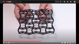
Auxetic Surfaces Metamaterials
Perforated surfaces that deform in special Materials whose behavior flows from the material’s
ways, e.g. along an undulating surface. arrangement rather than its composition
Multi-Material Printing Parametric Form
Use of non-standard filaments, e.g with Form from a parameter-driven program
conductive, flexible, or metallic properties, that automatically generates geometry
in addition to standard plastics like PLA
STEP 3
Start Small
START SMALL
The first part of step 3 is giving yourself the tools needed to succeed.
That means nailing the fundamentals: use filament matched to the functional requirements of your widget (rubber-like TPU for flexible mechanisms, PETG for impact-resistant tools, PLA for figurines...), run extrusion temperature and clearance tests, restart the print as many times as necessary to get perfect first layer adhesion, etc.
Don’t settle for sagging or stringing. Given proper tuning, most $300 machines can produce results 90% as good as their $3,000 cousins.
Once your hardware is in working order, do the same with your desktop environment. We recommend using a Github-like branched workflow in CAD (more on this here), making your progress legible and backtrack-able.

Don’t be left praying control-Z goes back 100 steps when v5 calls for the piece from v1
So your hardware and workflow are sorted. Is it time to start CADing yet? No. Once more unto the breach, fellow makers.
Translate your research into a list of detailed constraints; the legs must support 5 kg of weight, the corners must be snag-proof, the part must not topple when prodded. The potential solution space is overwhelmingly vast, so the longer your constraint list the better.
When software architects build an application, they begin with the development of working microservices, unit testing each one in turn. The whole emerges from the pieces. The same applies here.
Forget that you’re making, oh, a tape dispenser. CAD up a cylinder to hold the tape roll. Print it. Once the roll nests comfortably and the halves bend without snapping, move on. CAD up a serrated edge and print it. Once it cleanly slices a piece of scotch, move on...
STEP 4
Go Big
GO BIG
Thanks to the previous phases, you’ve uncovered the core functional requirements and refined accordingly your internal clearances, massing, ergonomics, etc.
At long last, give yourself permission to think aesthetics. While there are plenty of sophisticated ways to enhance the look and feel of your part, beginning CAD designers will be best served by starting with a ‘geometric grammar’.
A geometric grammar is not too different from, say, Spanish grammar. Just instead of ‘subject -> verb -> object’ use ‘gap of 3mm’ -> ‘followed by a column that’s a multiple of 3mm’ -> ‘terminating in a 1mm chamfered edge’.
Yes, there will be irregular verbs. Perhaps the lip of your tape dispenser requires a bezier curve that’s at odds with the vocabulary of 30’, 60’ and 90’ angles you’ve created for the body. Fine - just use the bezier sparingly.
Experienced CADers might consider adding ornament at this point. This could include assets, such as parametric scripts, or geometric motifs you’ve developed over the course of other projects.

A parametric script can panel complex geometry, like light baffles, over complex surfaces, like a curvy roof
Regardless of how you arrive at the overall form, you mustn’t be precious about it. New functional constraints often appear. When your roommate points out that your print stabs her wrist when rotated half a turn, rather than trusting the user (never trust the user) to avoid rotating it the wrong way, make the fix and reboot the aesthetics.
Some call it stupid proofing, we call it old fashioned decency.
Finally, upload your design to Thingiverse or similar. Not only does this grow our community, it gives fellow makers the chance to remix and improve your work. If you’re lucky, your brainchild will take on a life of its own.
Happy making!